Last updated: September 13, 2020
In this article we will learn about the hydraulic tank basic concept, its design, tasks, components, the importance of pressure ratio in a hydraulic tank, which component is responsible for which task & hydraulic tank types. So, be ready for an adventurous journey of knowledge.
Hydraulic fluid is the media that transfers force with the help of pressure & flow. Therefore, the amount of hydraulic fluid is very important in a hydraulic system and it depends on force multiplication and motion multiplication. For example,


We have read in How hydraulic works: Basic- Part-I that how simple hydraulic jack works and help to lift heavy load such as car’s wheels. For example, in figure 2 this amount of hydraulic oil is not sufficient for lifting tire enough to change. So, what we can do?
Here is some solution for that situation.
- Either lengthen the stroke of the pump. Means increase the pump’s cylinder length.
- Either reduce the area of the lifting cylinder.
- Top up the hydraulic fluid and pump again.
By the first method, you can make available more hydraulic fluid to pump, however, it is not convenient because it makes the jack bulkier, bigger and heavier. So, it is not an applicable daily practice.
The second answer, reducing the area of lifting cylinder will reduce the consumption of hydraulic fluid and cause long-stroke,
The third solution is best and suitable. we can top up the fluid from a separate supply of fluid and pump again as much we need.

Introduction of the hydraulic tank in the system
In this diagram, we are seeing a hydraulic tank that provides fluid to the system whenever needed and directed back to the hydraulic tank when it is no longer needed. In this diagram, we also see two flap gate (check valve)
To lift the vehicle, the hydraulic fluid is pumped out of the hydraulic tank and into the lifting cylinder while
But the hydraulic tank is not only for storing the hydraulic fluid. Now we will find a more significant purpose of a hydraulic tank.
Hydraulic tanks do not just hold hydraulic fluid; they often full fill other tasks, such as:
- Calming the hydraulic fluid.
- Gas purging.
- Cooling Hydraulic Fluid.
- Cleaning the hydraulic fluid.

Calming hydraulic oil is one of the most important tasks for a hydraulic tank. The liquid might flow very quickly back into the tank. That can cause the formation of foam and air inclusions. The pump should not suck them in. That is why the tank has to be constructed so that the flow calms down well.

Gas purging is also one of the hydraulic tank’s tasks. The hydraulic fluid can contain air, for instance in the form of tiny air bubbles. This air in the tank must be able to escape from the liquid as much possible.

While we performing any hydraulic operation, hydraulic fluid gets heat up due to friction and it may also heat up due to working in high-temperature environments such as processing of hot red metal. Therefore, the hydraulic fluid must be cool down somewhere in a hydraulic system and this task is being done in a hydraulic tank.

In the hydraulic system, there are plenty of moving parts. Due to these moving parts wear and tear occurs. Also, seals will damage. These all unwanted particles are carried by the hydraulic fluid as dirt. So, the filtering of hydraulic fluids becomes much more important. Without filtering, if hydraulic fluid is used it may cause some catastrophic damage.
Now, we will see the basic design and component of hydraulic tank.
Basic Design of hydraulic tank or reservoir.
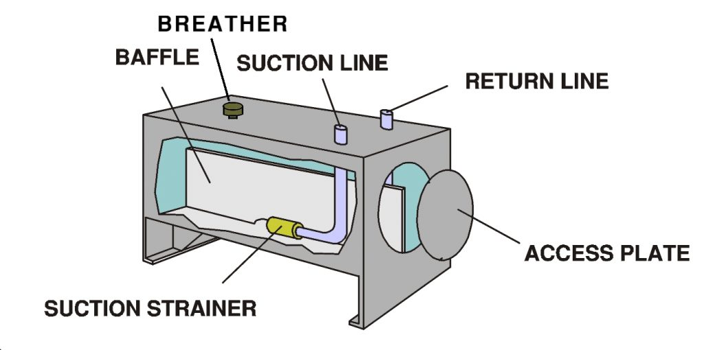
Suction Line:
The suction line connects the hydraulic tank to the pump. After that hydraulic fluid goes to the circuit. Suction pipes generally have a larger diameter as compared to return lines. Suction pipes have a smaller length so as to facilitate lesser loss and cavitation.
Return Line:
After performing the necessary task hydraulic fluid comes back to the tank by return line through the return manifold and return filter. The return line end should not be too high from the bottom of the reservoir as the too high an outlet will cause turbulence to the output flow. Normally the return line ends are taper cut to facilitate the flow direction towards the wall side. This will help the fluid to travel a larger distance so that it gets more time to cool.
Access Plate:
the access plate is for cleaning the tank.
Suction Strainer:
The strainer is placed in the suction line of the pump. This provides filtered hydraulic fluid to the pump. It typically has some filtering screens (for particles of a particular size) that filters the contaminants before going to the pump. This is periodically replaced to ensure uninterrupted flow.
Baffle Plate:
Baffle plates are normally the steel plates that are incorporated in the reservoir to divide the fluid into different chambers so that the fluid has to travel through other ways to get to the suction chamber from the return flow chamber. As a result, oil gets cool and contaminants set at the bottom of the chamber. It gives them time to hydraulic oil for suppressing, calming, and gas purging.
Breather:
This is the opening for equalization of air pressure when fluid level changes. A filter for a breather protects the fluid from dirt. It is important to understand that too small a breather cap or choked filter will cause a vacuum in the oil tank and cause cavitations in the pumps. So, it needs extra care.
Oil level gauge:
In a hydraulic tank, an oil level gauge shows the level of oil. commonly there are two lines in gauge. one for a high level and one for a low level.
Filler cap:
The filler is for top-up the hydraulic oil.
Next, we will see Processes in the hydraulic tank and combine all tasks of a hydraulic tank.
Processes in the hydraulic tank
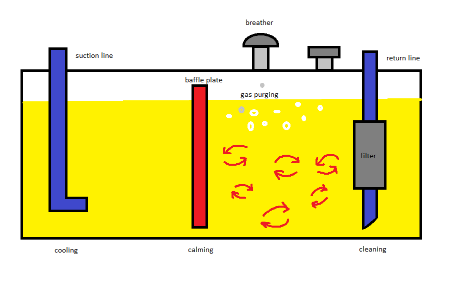
The return-line filter first cleans dust particles from the recycled hydraulic fluid. The liquid still has a strong current upon entering the re-circulation area. The calming baffle suppresses the flow’s motion and prevents it from spreading to the suction area. Any air bubbles that might be present rise to the surface of the liquid and escape into the tank. Excess air escapes from the tank to the outside via a breather (ventilation and exhaust). The liquid flows into the suction area through openings in the calming baffle’s floor area. The liquid dissipates heat to the outer air over the hydraulic tank’s entire surface, thereby cooling it.
Types of hydraulic tank or reservoir
For the proper function of a pump, the pump needs a continuous feed of fluid. And therefore, the pressure at the suction line must be great enough. When the tank is full, the pressure at the inlet will be great enough (liquid pressure + atmospheric pressure). That is why much fluid is available for suction but if the fluid is just above the inlet then the pressure will be less enough and cause less fluid available for suction which can create a cavity in the pump.
In this way, we can categories hydraulic into two types.
- Atmospheric tank
- Pressure tank.
Atmospheric Hydraulic Tank
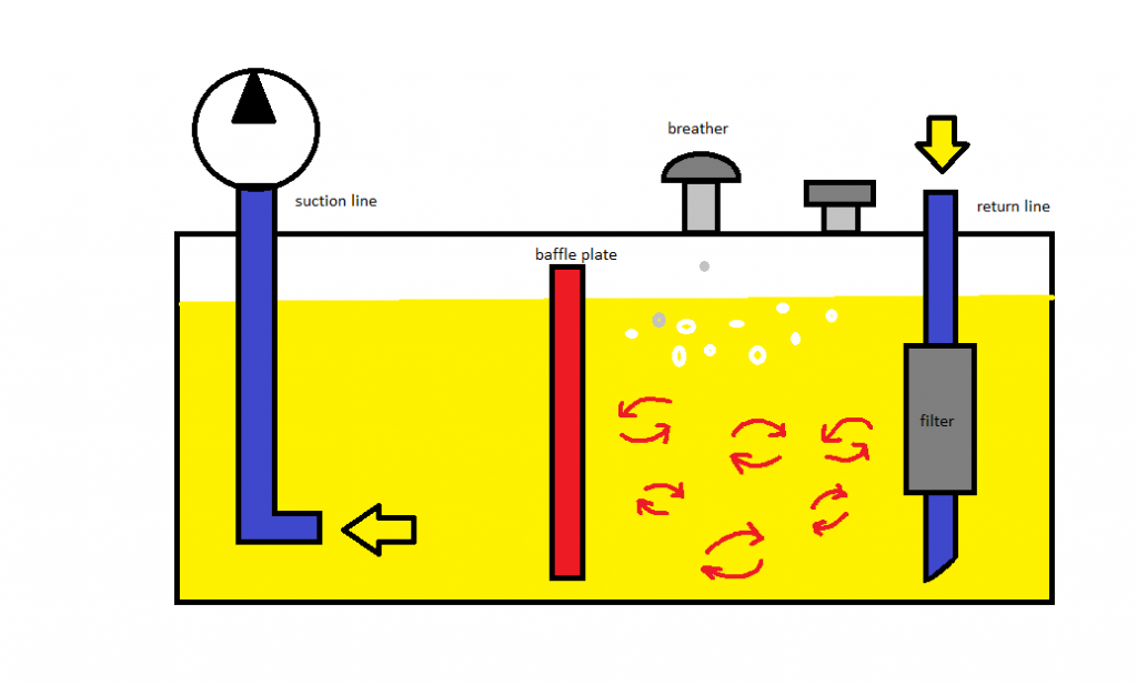
Atmospheric Tank: Because of the atmospheric tank is open with the atmosphere via a breather so, pressure on the suction line depends only on the liquid level. Hence, we can not increase the pressure anymore. The total pressure will be the sum of pressure due to liquid level and atmospheric pressure
Pressurised Hydraulic Tank
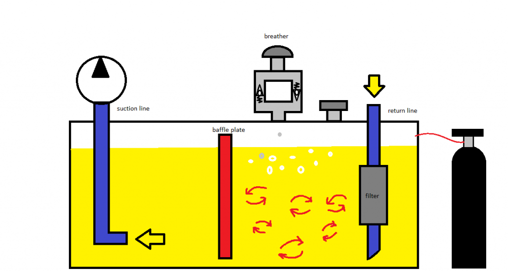
Pressure tank: In a pressure tank firstly, pressurized air is fed from external to maintain the required pressure, and the second thing pressure regulator is added for regularising the pressure. As a result, if pressure exceeds the required pressure a spring-loaded check valve releases the pressure and if pressure is lowered below the atmospheric second check valve will allow atmospheric air into the tank.
We have completed all the basics of hydraulic tank and their types. Hope you learned something and will come soon for another interesting article. Till then bye-bye. Thank you.
Can you explain the hydraulic oil storage tank capsize?