Hydraulic system designing is a complex process. Although we will discuss what are the basic requirements of hydraulic engineers for designing. Before the design of the overall hydraulic system, the Hydraulic Engineer must first consider the requirements for the system prior to selecting which type of components will be used in the design.
For example, consider a system that only requires one pump to deliver oil to a double-acting cylinder. The designer may select a variable displacement piston pump over a fixed displacement gear pump. Because a variable displacement pump will de-stroke when no flow is required and therefore reduce power consumption and improve performance. Here we have listed many other factors that need consideration for designing a hydraulic system.
What are the factors for designing a hydraulic system?
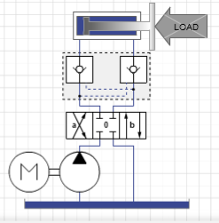
Let us design a simple double-acting cylinder operation. For this simple hydraulic system, we need to answer the following questions.
- What is the duty cycle of the actuator?
- How to calculate maximum working pressure in the system?
- What is the maximum flow required by the system?
- How to calculate the required pump size (cc/rev)?
- What should be the maximum rpm of the pump?
- What elevation will the system be operating at?
- ISO 4406:2017 cleanliness level?
1. What is the duty cycle of the actuator?
Answer: Defining the duty cycle of the actuator is very important for a hydraulic system. The duty cycle is the number of strokes per hour. If the duty cycle is very less (4-6 strokes per hour) than the cleanliness level (i.e. ISO 4406:1999) can not be achieved with a variable displacement pump. Because when there is no cylinder actuation, the pump will de-stroke and stop the oil flow. The only oil flow is from the pump’s casing. Moreover, any pump manufacturer does not recommend any restriction in case drain including filter.
So, the duty cycle of an actuator is important for selecting pump type and cleanliness of the hydraulic system.
2. How to calculate maximum working pressure in the system?
Answer: The maximum pressure depends on the two factors. First is the maximum force that the cylinder will handle and the second is cylinder bore size.
Once the required force is known along with the cylinder bore, the designer can calculate hydraulic pressure in the cylinder using the calculation shown below.
P = F/A
 P = Pressure (N/m2)
 F = Force(N)
 A = Area (m2)
Once working pressure at the cylinder is determined the designer will need to determine which type of hydraulic connection will be used. He must ensure that the working pressure of the connection meets or exceeds the pressure required at the cylinder.
3. What is the maximum flow required by the system?
To calculate the maximum flow required for the system, the designer will need to know the required extend and retract times for the cylinder. And also the diameter of bore, rod, and length of stroke.
4. What size of the pump should use?
The selection of the pump size depends on the flow required by the hydraulic system. A pump can be measure in cc/rev (cubic centimeter per revolution). Bigger the size of the pump means it can displace more liquid per revolution and hence more flow. And smaller the pump, lesser the flow.
5. What should be the maximum rpm of the pump?
Normally an electric motor or engine drives the pump. To achieve the desired rpm of the pump designer either use VVVF drive or gearbox. RPM of the pump is also a factor of flow calculation. Higher the rpm means higher the flow. Thus flow, size of the pump, and rpm of the pump are related to each other.
So, a hydraulic engineer or designer can select a smaller pump if the rpm of a pump can increase. Similarly, if the rpm of a pump is not in his control than, he has to increase the pump size to fulfill the flow demand in the hydraulic system.
6. What elevation will the system be operating at?
Once maximum pressure, flow, rpm, and pump size calculation has done, it is very important for a pump in a hydraulic system to meet the minimum inlet condition. For this, maximum elevation is specified by the designer at where the hydraulic system can work efficiently. For example:
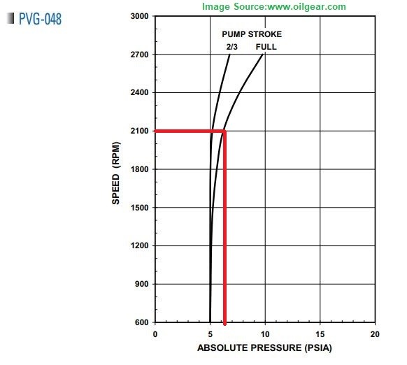
Take a PVG-048 pump. At the speed of 2100 rpm, the minimum inlet pressure should be 6.2 psi. The atmospheric pressure at sea level is 14.7 psi which is higher than the recommended inlet pressure. But if the hydraulic system has to work on 25000 feet above the sea level ( atmospheric pressure will be only 5.45 psi), then there is a problem. It may damage the pump due to cavitation.
7. ISO 4406:2017 cleanliness level?
we have already discussed every factor as per the designing aspects. But the designer may have to consider all of the design if it does not meet the required cleanliness level.
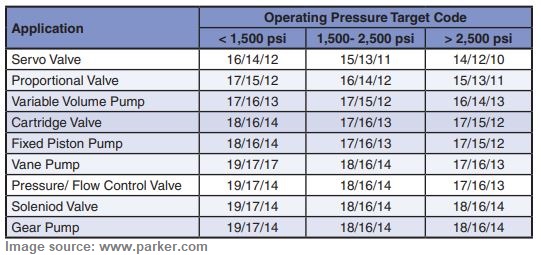
The required ISO 4406:2017 (previously ISO 4406:1999) cleanliness level will depend on what type of components are using in the hydraulic system. For instance, gear pumps are more tolerant to contamination than piston pumps. Similarly on/off valves are more tolerant of contamination than proportional valves. The cleanliness recommendation for different components are showing below:
Conclusion
“How to design a hydraulic system” is a long and tricky process. Although here we tried to design a simple double-acting actuator circuit and discussed some basic considerations. If you are designing a complex hydraulic circuit with more than two operations, you have to consider many more factors that will play key roles in the circuit. Such as cooling of fluid, fluid viscosity, types of fluid used, tank size, etc.