
Last updated: February 9, 2020
The industrial hydraulic symbol or just the hydraulic symbol is the first step towards an understanding of the hydraulic system. Without a basic understanding of symbols, one cannot efficiently troubleshoot the hydraulic system completely. A hydraulic system consists of cylinders, motors, valves, and pumps connected via hydraulic hoses and pipes. Due to the complexity of showing these components in a diagram we use symbols instead of absolute components.
Industrial Hydraulic Symbol
Most hydraulic industries follow standard DIN ISO 1219 for the design of hydraulic circuits, however, one can find differences in individual drawings with the company.
The symbols in a hydraulic schematic give the following information about the system:
- Type of Prime mover (Engine or Electric Motor)
- General information about pump (CC/rev & RPM)
- The number of connections and joints for the representation of the hydraulic flow.
- Different types of valve and their functions.
- The number of switching positions of the valves.
- Actuation and return method of the valves.
Although we get all necessary information from schematic and symbols, it can define the following details:
- The exact location of the components.
- Dimensions of the component.
- Manufacturer of the components.
Now, by keeping the intention of a hydraulic schematic in mind, one can understand the basic symbol for the hydraulic system very easily.
Basic hydraulic symbols
 | Pressure line or Return line. |
 | Quick release coupling. |
 | Shuttle Valve. |
 | Pressure Gauge. |
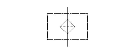
 | Multiport Swivel. |
 | Manifold |
 | Line Junction. |
 | Connection for measuring port. |
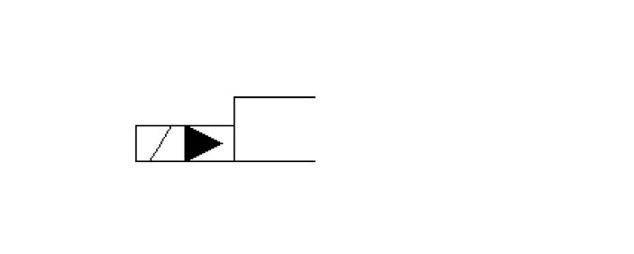
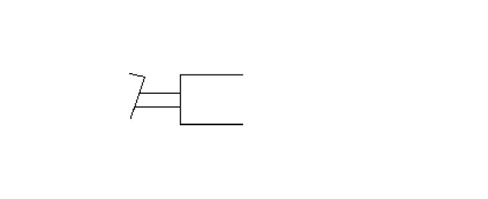
Symbols for actuation type
 | Actuation by pneumatic (compressed air). |
 | Actuation by spring force. |
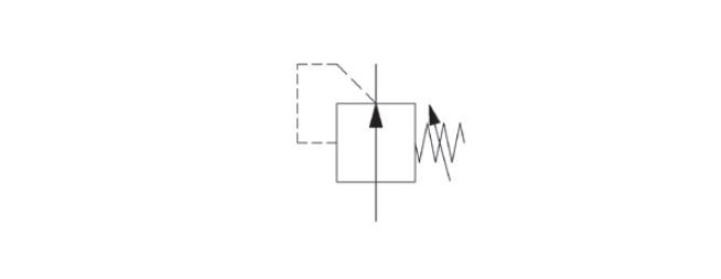
 | Actuation by Hydraulic pressure. |
 | Actuation by the plunger. |
 | Actuation by the roller movement. |
 | Actuation by solenoid (electrically) |
 | Actuation by electro-hydraulically. |
 | Actuation by foot paddle. |
 | Actuation by a lever. |
Symbols for filters and coolers
 | Filter |
 | Cooler |
Symbols for Valves
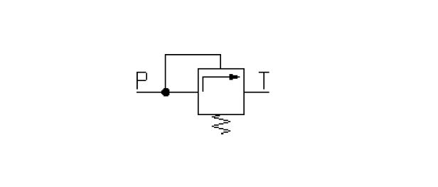 | Pressure Relief Valve (non-adjustable) |
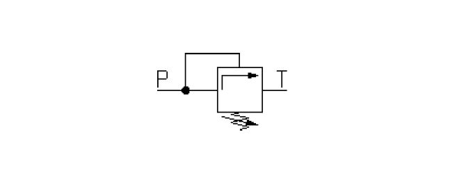 | Pressure relief Valve (adjustable) |
 | Check Valve |
 | Pilot Operated Check Valve. |
 | Pressure reducing Valve |
 | 3 Port Pressure Reducing Valve |
Symbols for Pump and Motor
 | Mono direction fix displacement pump |
 | Mono direction variable displacement pump |
 | Mono direction fix displacement motor |
 | Mono direction variable displacement motor |
 | Bi-directional fix displacement pump |
 | Bi-direction variable displacement pump |
 | Bi-direction fix displacement motor |
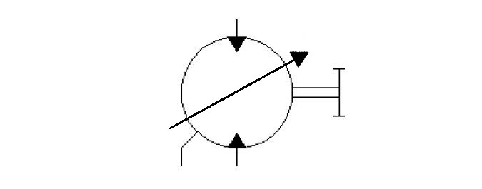 | Bi-direction variable displacement motor |
 | Electric Motor |
Symbols for Cylinders
 | Single Acting Cylinder |
 | Double Acting Cylinder |
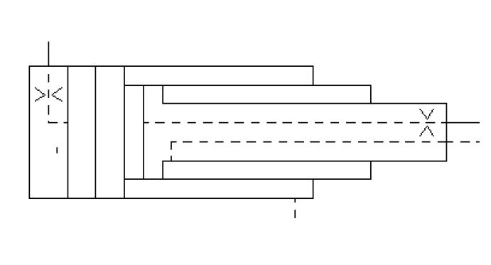 | Telescopic Cylinder |
FAQ
(Que.1) What is the hydraulic symbol for concrete pumps?
Answer: The symbol will be the same for all pumps. Concrete pumps are designed differently because it has to handle dense liquid or semi-solid materials, but the symbol will be similar. See the Symbol