Last updated: February 10, 2019
In

As shown in figure 1. the pump will make the fluid to flow and extend the piston and does work. But, after complete extension, we can not retract the piston which is not intended. Therefore, we need something which makes our system repetitive. This is Direction control valve or in short DCV.

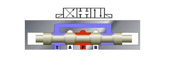
In the above figure 2. a hydraulic direction control valve (DCV) is used. In the central position, the cylinder will stay in its place and valve will be called in 0 positions or in the rest position. However, if it changes the position from 0 to b cylinder rod will extend. Similarly, when direction control valve changes its position from b to a cylinder rod will retract. Thus Hydraulic direction control valve makes the system repetitive and useful and we can get benefited to continue work.
Graphical symbol

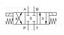
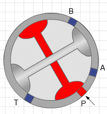
Although the graphical symbol of the direction control valve depends on the number of port and number of position, however, figure 3 shows a general idea of the symbols. Here the number of square boxes indicates the number of positions whereas arrows indicate the direction of flow through the valve. Similarly, Closed paths show close ports. A and B are the working ports. P is the port connecting with the pump while T is the port connecting to the tank. So, this is a 4/3 direction control valve with 4 ports and 3 positions.
Here are some symbols of various hydraulic direction control valve

2/2 Direction Control Valve
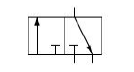
3/2 Direction Control Valve
3/3 Direction Control Valve

2/2 Direction Control Valve

4/3 Direction Control Valve

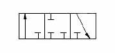
5/2 Direction Control Valve

5/3 Direction Control Valve

6/3 Direction Control Valve
Controlling the hydraulic direction control valve
The hydraulic direction control valve can be controlled in various ways. However here are some mentioned.
- Mechanically controlled.
- Electrically controlled.
- Pneumatically controlled.
- Hydraulically controlled.
- Controlled by combination of any of above.
The direction control valve either can be

Illustrated
spring centred electrically operated DCV
Illustrated

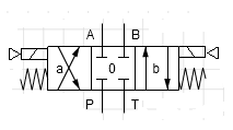
spring centred Pneumatic operated DCV
Illustrated

spring centred electro-hydraulic operated DCV
Illustrated
spring centred electro-pneumatic operated DCV
Illustrated
Hydraulic direction control valve types
- Spool type
- rotary type
Spool type

Rotary type
Spooling Position of 4/3 hydraulic direction control valve
- Open centre: In this 4/3 DCV all the ports are connecting with each other in centre position.

2. Close Center: In this 4/3 DCV all the ports are blocked in center position.
3. Float center: In this 4/3 DCV pressure port is block but working ports are connected with the tank in cente position.

4. Tandem Center: In this 4/3 DCV, pressure port and tank port are connected in center position but working ports are blocked.

So, this is the brief description of Hydraulic direction control valve. Hope you learned something.